Physics field notes / Voyager

Wave motion
and foil forces.

Voyager builds an ocean from traveling wave components, then computes foil forces from the water flowing past each wing. These notes describe the equations, riding inputs, and gameplay assists used by the model.

  1. 01 Wave components
  2. 02 Foil forces
  3. 03 Turn and trim
  4. 04 Wave energy
Illustration of crossing wave components and a submerged hydrofoil with lift and drag equations
Concept illustration The formulas are tied to the model described below. The rendered flow is explanatory artwork rather than a CFD result or gameplay capture.

01 / Ocean

A surface made from many waves

The game adds directional components with their own amplitude, direction, phase, and frequency. The components can reinforce each other at one point and cancel a few meters away.

surface elevation

η(x, t) = Σ Ai cos(ki · x − ωit + φi)

A
component amplitude
k
wave number and travel direction
ω
angular frequency
φ
starting phase

How the model works

Deep-water dispersion

ω² = gk

Frequency and wave number are linked with the deep-water gravity-wave relation. Wind swell follows a JONSWAP-shaped spectrum, spreading energy across frequencies around a peak. The game combines seeded wind swell with directional ground-swell components and retains the strongest components for the surface calculation.

02 / Foil

How the foil meets moving water

The force calculation subtracts local water velocity from the wing’s velocity. That relative flow sets speed and the incoming flow angle at the front wing and stabilizer.

Hydrofoil force and angle-of-attack diagram A hydrofoil section meets water-relative flow at an angle of attack. Lift points perpendicular to the flow, drag points downstream, and banking tilts the lift vector. LOCAL WATER SURFACE INCOMING WATER FLOW α ANGLE OF ATTACK LIFT PERPENDICULAR TO FLOW DRAG WITH THE FLOW BANK TILTS SUPPORT
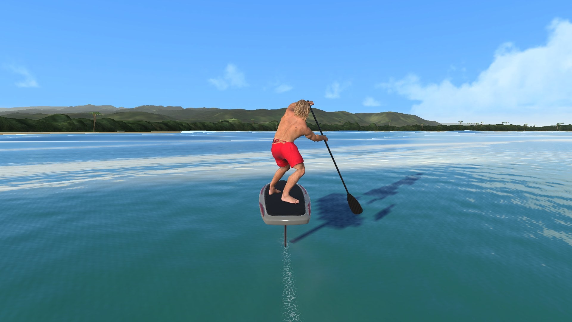
The model gets angle of attack from craft pitch, vertical flow, wing incidence, and rider trim. The arrows show water moving past the wing. Lift is perpendicular to that flow; drag acts with it, opposing the wing’s motion through the water.

Lift

L = ½ρv²SCL

Water density ρ, water-relative speed v, wing area S, and lift coefficient CL set the force.

Drag

D = ½ρv²SCD

The same square-law pressure drives drag. Doubling speed gives four times the force if the coefficients and immersion stay fixed.

Finite span

Lift slope and induced drag

CLα = 2π / [1 + 2π / (πeAR)]
CDi = CL² / (πeAR)

The model uses e = 0.9. Finite span reduces the ideal two-dimensional lift slope, while induced drag rises with the square of lift coefficient.

Operating limits

Stall and breach

Before stall, lift coefficient grows with angle and stops at the foil’s configured maximum. Past the stall angle, the model decays lift. As a wingtip nears or crosses the surface, the immersion multiplier removes most of its support and adds a near-surface drag penalty.

03 / Ride decisions

What speed, trim, and bank change

Speed, trim, bank, and immersion change together. Where the next face is moving affects the input you need to make the connection.

Your moveModel responseWhat you feel

Build speed

Dynamic pressure rises with v², increasing lift and drag together.

The foil feels firmer as speed rises, while poor trim costs more drag.

Add front-foot pressure

A press adds an 800 N forward boost for at least two seconds, up to four while you hold it. A two-second, 40 N drag follows on flatter water, and a descending face waives that drag. Holding it on the flats for more than four seconds sinks the foil.

Use a short press to build speed, then release. The tradeoff changes when you are already driving down a useful face.

Bank into a turn

The required wing lift grows as 1/cos(bank). Lift-induced and spanwise turn drag can rise with the load.

A hard bank redirects support into the turn, with less margin left to hold height.

Ride high

Tip immersion shrinks near the surface, reducing lift support and increasing the chance of a breach penalty.

The ride can feel free until a tip ventilates, then support drops abruptly.

04 / Wave energy

Wave energy, guidance, and stamina

The learning logic estimates which nearby faces can help the ride. Physical wave energy describes the wave field and carries units. The rider’s on-screen energy percentage is a separate stamina budget for efforts such as pumping.

Learning cue / unitless

cue = smooth[(height² + steepness²) / scale]

The game samples a reduced set of components, normalizes local height and slope, and clamps the result from 0 to 1. It uses that proxy to rank reachable faces and estimate support. The number is useful for guidance, but it is not joules.

Regular wave / J m−2

E = ⅛ρgH²

For a regular linear gravity wave with height H, mean total energy per horizontal area is one eighth of density times gravity times height squared. The engine also groups spectrum components into directional packets and computes an energy-like J/m² value before deriving flux from group velocity.

Coastal lab / teaching model

Why waves turn near shore

In finite depth, the dispersion relation becomes ω² = gk tanh(kh). The shallow side of a crest slows first. Over a simple shelf, crests become more parallel to shore as their travel direction turns toward it. NOAA’s refraction material shows how that bending can spread or concentrate wave energy along a coast.

Site-only illustration

The coastal lab uses this finite-depth idea for teaching. Voyager’s gameplay ocean does not sample bathymetry or refract swell. At Turtle Bay it does shelter the water behind the coast, which is a separate, simpler effect.

Sources and further study

Follow the derivations

NASA’s pages use airfoils in air, but the nondimensional lift and drag relationships also apply to a hydrofoil when density and velocity are taken from the water flow. MIT’s ocean engineering material covers the water-specific theory and its limits.

Voyager uses a simplified real-time force model with explicit gameplay assists. It is not a CFD solver, an engineering design tool, or a claim that every operating condition has been measured.